1 / 5
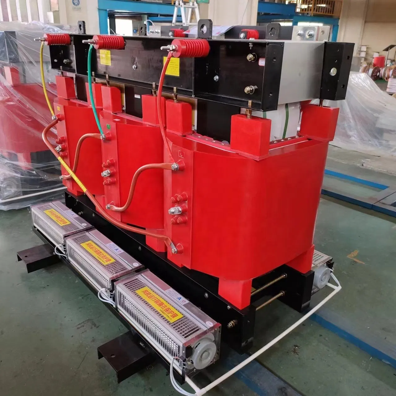
Compared with transformers using silicon steel sheets as iron cores, the no-load loss is reduced by more than 70% and the no-load current is reduced by about 80%.
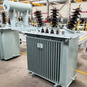
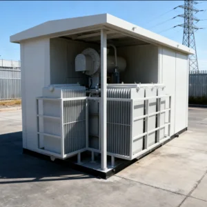
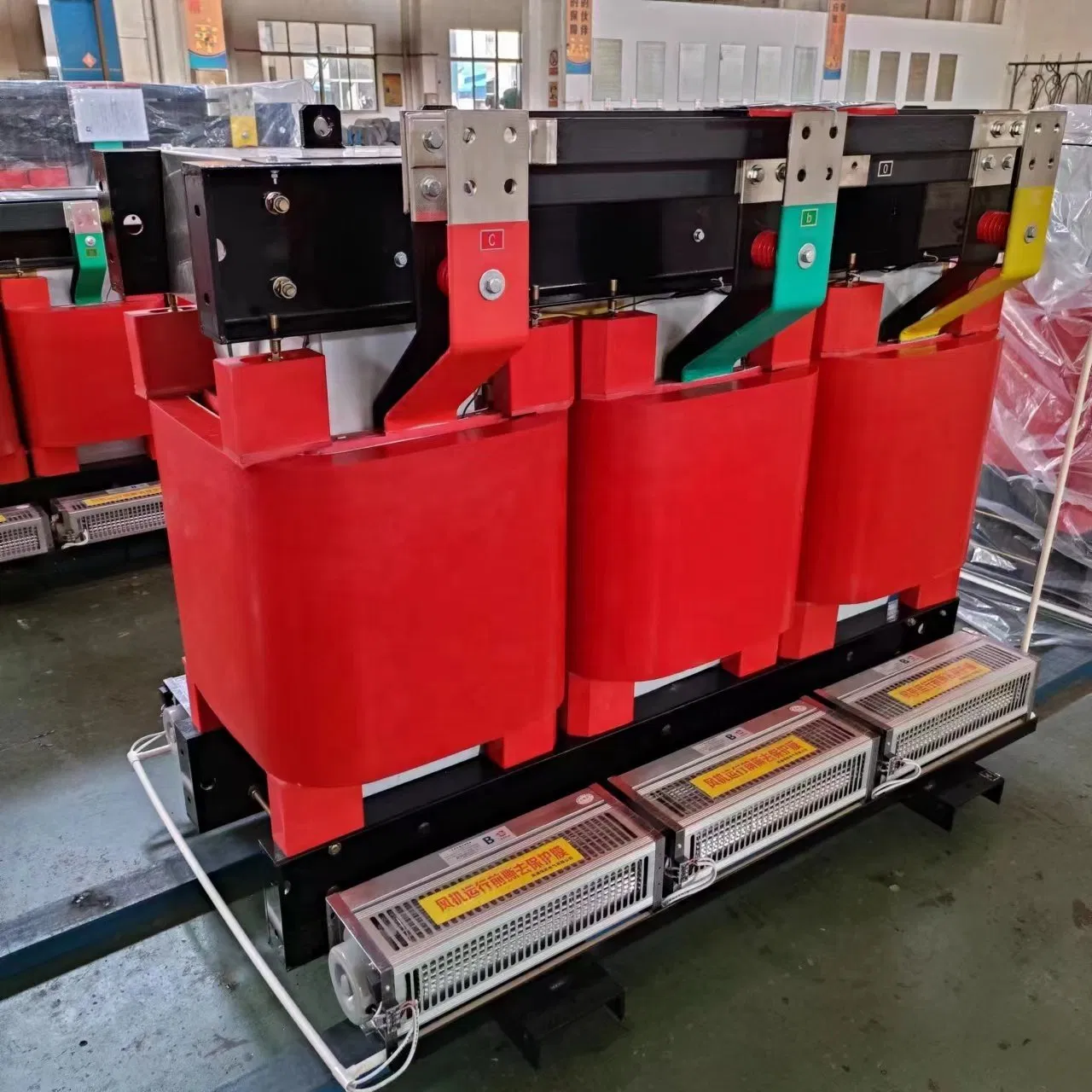
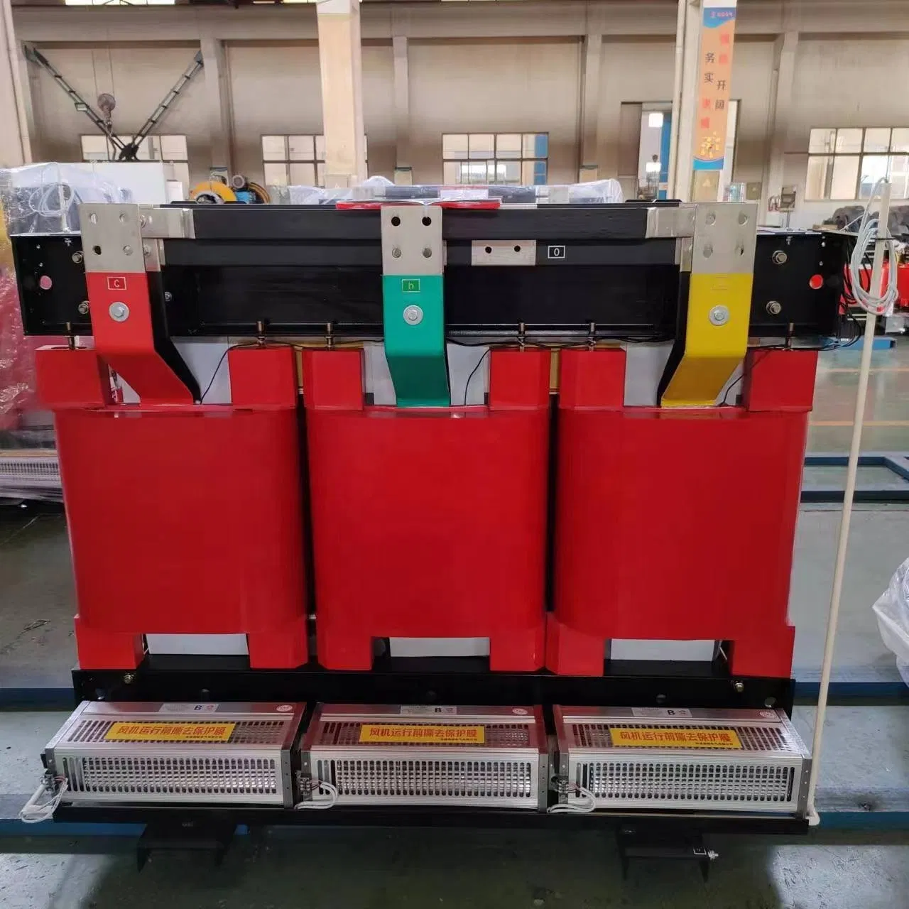
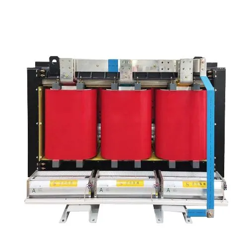
Significant energy savings (standby electricity reduction) are achieved using transformers that employ amorphous alloy. This is particularly effective in public facilities, tall buildings where electricity usage fluctuates, photovoltaic systems with low actual operation rates, and industrial buildings.
| Rated Capacity (KVA) | Vector Group | Voltage Combination (KV) | No-load Current (%) | Load Loss (W) at Temp Rating | No-load Loss (W) | Short Circuit Impedance (%) | ||||
|---|---|---|---|---|---|---|---|---|---|---|
| H.V. | Tap Range | L.V. | B (100ºC) | F (120ºC) | H (145ºC) | |||||
| 30 | Dyn11 | 6/10/11 | ±5% / ±2×2.5% | 0.4 | 1.6 | 635 | 675 | 720 | 70 | 4.0 |
| 50 | Dyn11 | 6/10/11 | ±5% / ±2×2.5% | 0.4 | 1.4 | 895 | 950 | 1015 | 90 | 4.0 |
| 100 | Dyn11 | 6/10/11 | ±5% / ±2×2.5% | 0.4 | 1.2 | 1405 | 1490 | 1605 | 130 | 4.0 |
| 250 | Dyn11 | 6/10/11 | ±5% / ±2×2.5% | 0.4 | 1.0 | 2460 | 2620 | 2810 | 230 | 4.0 |
| 500 | Dyn11 | 6/10/11 | ±5% / ±2×2.5% | 0.4 | 0.8 | 4360 | 4635 | 4970 | 360 | 4.0 |
| 1000 | Dyn11 | 6/10/11 | ±5% / ±2×2.5% | 0.4 | 0.6 | 7265 | 7725 | 8320 | 550 | 6.0 |
| 2500 | Dyn11 | 6/10/11 | ±5% / ±2×2.5% | 0.4 | 0.5 | 15340 | 16310 | 17525 | 1200 | 6.0 |