 Tanaka Electric
Integrating a power transformer substation is not simply a matter of connecting equipment and energizing the bus. It is a coordinated engineering process involving transformer specifications, protection systems, grounding, control logic, civil works, and communications. A small mismatch can create serious consequences. A poorly sized cable tray may delay installation. An incorrect relay setting may interrupt healthy equipment.
John D. McDonald, a widely recognized substation automation specialist, captures this practical concern: “A substation is only as reliable as its weakest interface.” His observation reflects the purpose of this Power Transformer Substation Integration Guide. Successful projects depend on clear interfaces between transformers, switchgear, SCADA, protection relays, and the utility network.
The guide examines ten integration tips for safer and more dependable project delivery. It considers transformer ratings, impedance coordination, short-circuit studies, grounding grids, surge protection, and factory acceptance testing. It also addresses communication protocols, including IEC 61850, because digital signals still require careful validation. Field teams should inspect marshalling cabinets, torque connections, cable labels, and alarm points before commissioning.
Details matter greatly.
However, no integration plan is perfect. Site conditions change. Drawings may contain outdated assumptions. Teams can also underestimate maintenance access around radiators, bushings, and tap changers. That weakness deserves honest review, not concealment. Experience shows that repeated inspections, documented testing, and independent technical checks often prevent expensive corrections later. This introduction sets the foundation for the ten practical recommendations developed throughout the guide.
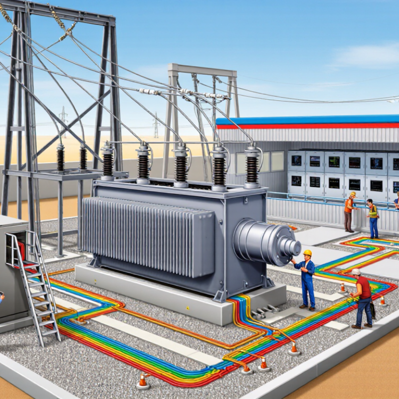
Top 10 Power Transformer Substation Integration Tips: Define Power Transformer Substation Integration Requirements
Power transformer integration starts with a written requirement, not a purchase request. Record voltage levels, continuous load, emergency loading, short-circuit duty, impedance, frequency, tap range, and cooling method. Include future demand, not only today’s peak. The U.S. Department of Energy’s Electric Grid Supply Chain Review notes that large power transformers may require lead times of up to 36 months. A missing specification can therefore become an expensive delay. Define insulation levels, altitude, ambient temperature, seismic conditions, noise limits, fire protection, and physical clearances. Keep assumptions visible. They change.
Tip: Build a requirement matrix with owner, value, tolerance, and verification method. Confirm every interface between the transformer, switchgear, protection system, civil works, and control network. A practical site walkdown often exposes restricted crane access, cable-bending problems, or inadequate oil containment. Drawings alone miss these details.
Use measured load data where possible. Separate normal, seasonal, motor-starting, and contingency conditions. Specify protection zones, instrument-transformer accuracy, grounding impedance, differential protection, and communication timing. IEEE transformer standards can guide technical requirements, while the International Energy Agency’s Electricity 2024 report highlights rising grid investment needs as electrification expands. That pressure makes adaptable designs valuable. Still, flexibility should not mean vague requirements. An oversized transformer may waste capital and increase fault energy. An undersized unit may overheat during recovery events. Recheck the model with operations staff. The first version is rarely complete.
| No. | Integration Requirement | Requirement Definition | Typical Engineering Data | Verification and Deliverable |
|---|---|---|---|---|
| 1 | Define the Load Profile | Establish present demand, forecast demand, load diversity, power factor, motor-starting duty, and critical loads before selecting the transformer rating. | Peak demand in MW or MVA; annual load-growth assumption; minimum and maximum power factor; continuous, cyclic, and emergency loading conditions. | Approved load-flow study, 10–20 year forecast where applicable, transformer loading schedule, and defined normal/emergency operating cases. |
| 2 | Select Voltage and Transformer Rating | Match primary and secondary voltages, frequency, phase arrangement, and rated power to the utility network and connected equipment. | System frequency: 50 or 60 Hz; three-phase operation; common substation voltage classes include 11, 33, 66, 110, 132, 220, and 400 kV; rating expressed in MVA. | Single-line diagram, transformer data sheet, voltage-ratio schedule, vector-group specification, and tap-range definition. |
| 3 | Establish Insulation Coordination | Coordinate transformer insulation levels with system overvoltages, lightning exposure, switching surges, and surge-arrester protective characteristics. | Rated withstand levels defined by the applicable insulation standard; lightning impulse withstand commonly specified in kV peak; power-frequency withstand specified in kV RMS. | Insulation-coordination study, selected arrester ratings, minimum clearances, creepage distances, and impulse-test requirements. |
| 4 | Calculate Fault Current and Impedance | Define transformer impedance and short-circuit withstand so the equipment remains compatible with upstream and downstream fault levels. | Percentage impedance typically specified on the transformer rating base; common power-transformer values are approximately 6%–18%, depending on voltage and rating. | Short-circuit study, three-phase and single-line-to-ground fault levels, mechanical-force assessment, and equipment short-circuit ratings. |
| 5 | Define Cooling and Thermal Limits | Specify the cooling method, ambient conditions, temperature-rise limits, overload duty, and the required alarm or trip functions. | Cooling designations may include ONAN, ONAF, OFAF, or equivalent; ambient design basis often includes 40 °C maximum unless the site standard requires another value. | Thermal-performance calculation, cooling-stage logic, fan and pump control scheme, temperature alarm/trip settings, and emergency loading profile. |
| 6 | Coordinate Protection and Control | Define electrical, mechanical, and fire-related protection interfaces, including transformer differential, restricted earth-fault, overcurrent, and temperature protection. | Protection functions selected according to system risk and transformer design; current-transformer ratios, accuracy classes, trip circuits, and breaker clearing times must be coordinated. | Protection-setting report, relay logic diagrams, trip matrix, interlocking schedule, control wiring drawings, and end-to-end functional-test records. |
| 7 | Specify Tap-Changer Requirements | Determine whether voltage regulation requires an on-load tap changer or an off-circuit tap changer, and define control, bypass, and synchronization requirements. | Typical on-load tap ranges are approximately ±10% to ±15% in stepped positions; exact step size and neutral position depend on the network voltage plan. | Tap schedule, automatic-voltage-control philosophy, raise/lower logic, parallel-operation scheme, mechanical-limit checks, and alarm list. |
| 8 | Integrate Earthing and Neutral Design | Define the transformer neutral connection, grounding impedance, touch and step-voltage limits, and the interface with the substation earth grid. | Grounding method may be solid, resistance, reactance, or resonant; earth-grid design must address maximum earth-fault current and permissible touch/step voltage. | Grounding study, earth-grid layout, neutral-grounding equipment specification, bonding schedule, and measured earth-resistance or impedance results. |
| 9 | Plan Mechanical, Civil, and Fire Interfaces | Confirm foundation loads, transport limits, oil containment, noise constraints, access clearances, cable routing, and fire separation requirements. | Design inputs include transformer shipping mass, operating mass, oil volume, footprint, radiated sound level, seismic category, and required maintenance clearances. | General-arrangement drawing, foundation and anchor plan, bund or oil-containment calculation, fire-risk assessment, lifting plan, and access review. |
| 10 | Define Testing, Commissioning, and Data Exchange | Specify factory tests, site tests, communications, monitoring points, documentation, and acceptance criteria before energization. | Typical checks include winding resistance, ratio and vector-group verification, insulation resistance, dielectric tests, oil quality, bushing tests, alarm checks, and functional trip tests. | Approved inspection and test plan, factory acceptance records, site acceptance records, communication-point list, as-built drawings, operation manuals, and energization approval. |
Engineering values are representative planning ranges only. Final ratings, insulation levels, protection settings, clearances, and test criteria shall be established from the applicable grid code, project specifications, and current electrical standards.
Record voltage, continuous load, emergency load, short-circuit duty, impedance, frequency, tap range, and cooling method. Include future demand. Also define insulation levels, altitude, temperature, seismic conditions, noise limits, fire protection, and clearances.
A matrix assigns each requirement an owner, value, tolerance, and verification method. It also exposes missing interfaces between the transformer, switchgear, protection system, civil works, and control network. Some assumptions will change.
It can reveal restricted crane access, tight cable-bending space, and insufficient oil containment. These problems may remain invisible on drawings. Visit the actual site.
Use measured data whenever possible. Separate normal, seasonal, motor-starting, and contingency conditions. An oversized transformer can waste capital and increase fault energy. An undersized unit may overheat during recovery events.
Rated power, impedance, vector group, and neutral arrangement must be selected together. They influence relay sensitivity, voltage drop, and breaker fault duty. Check the complete protection study.
Current-transformer saturation during an external fault can produce incorrect differential operation. Verify ratios, accuracy classes, and protection settings. The relay must distinguish magnetizing inrush from an internal fault.
Confirm the operating range, voltage targets, and time delays. They should match the control philosophy and system voltage profile. Also verify trip supervision, breaker-failure logic, lockout functions, and remote indications.
Simulate low oil level, high winding temperature, cooling failure, and transformer differential operation. Map every alarm to the correct control-room message. Do not rely only on factory documents. Field conditions can differ.
An independent review can find missed interlocks, grounding issues, cable-capacitance effects, and weak auxiliary supplies. One hidden mistake may delay commissioning. The first version is rarely complete.
A Power Transformer Substation Integration Guide should begin by clearly defining project requirements, including voltage levels, capacity, reliability targets, operating conditions, expansion plans, and applicable safety standards. A careful assessment of the site, grid capacity, environmental conditions, access routes, and expected electrical loads helps establish a practical and dependable design. Transformer selection should be coordinated with protection, control, metering, and communication systems so that all equipment operates as one compatible and responsive network.
Successful integration also depends on detailed planning for equipment placement, cable routing, grounding, lightning protection, fire prevention, access control, and personnel safety. Before energization, the completed substation should undergo systematic inspections and electrical testing, including insulation, wiring, protection, and functional performance checks. Commissioning should confirm that operating sequences and emergency responses work as intended. Finally, a clear maintenance plan should define inspection intervals, condition monitoring, documentation, spare parts, and corrective procedures to support long-term reliability and safe operation.
