Tanaka Electric Tanaka Electric

China Top Power Transformer Power Loss Reduction Methods?

Time:2026-10-08 Author:Sophia
0%

China’s power infrastructure is expanding, while electricity prices and carbon targets are increasing operational pressure. Power Transformer Power Loss Reduction Methods therefore deserve practical attention from utilities, factories, and renewable-energy developers. The strongest solutions combine sound design, accurate testing, and disciplined maintenance.

Dr. J. C. Das, author of Power Transformers: Design and Applications, states, “Transformer efficiency depends on controlling both no-load and load losses.” This principle remains highly relevant in China’s industrial networks. Engineers can reduce core losses through high-grade grain-oriented electrical steel, optimized magnetic flux density, and precise joint construction. Amorphous-metal cores may reduce no-load losses further, especially in distribution transformers operating continuously. Small details matter.

Copper or aluminum winding selection affects resistance, temperature rise, and lifetime. Larger conductors can reduce I²R losses, but they also increase weight and material cost. Transposed conductors, improved cooling channels, and balanced winding geometry can support better load performance. However, the best design is not always the most expensive one. Real load curves must guide decisions.

On-site teams should inspect oil temperature, bushing condition, connections, and cooling fans. Loose terminals may create visible hot spots during infrared inspections. Harmonic currents can also increase stray losses in factories using variable-speed drives. Filtering may help, but it requires measured evidence.

A limitation deserves honesty. Published loss reductions often reflect controlled laboratory conditions. Field results may differ because of aging, imbalance, overloads, and poor maintenance. Engineers should compare factory test data with quarterly operating records. That comparison reveals whether a promised saving is real, temporary, or overstated. The most reliable approach is measured, conservative, and continuously reviewed.
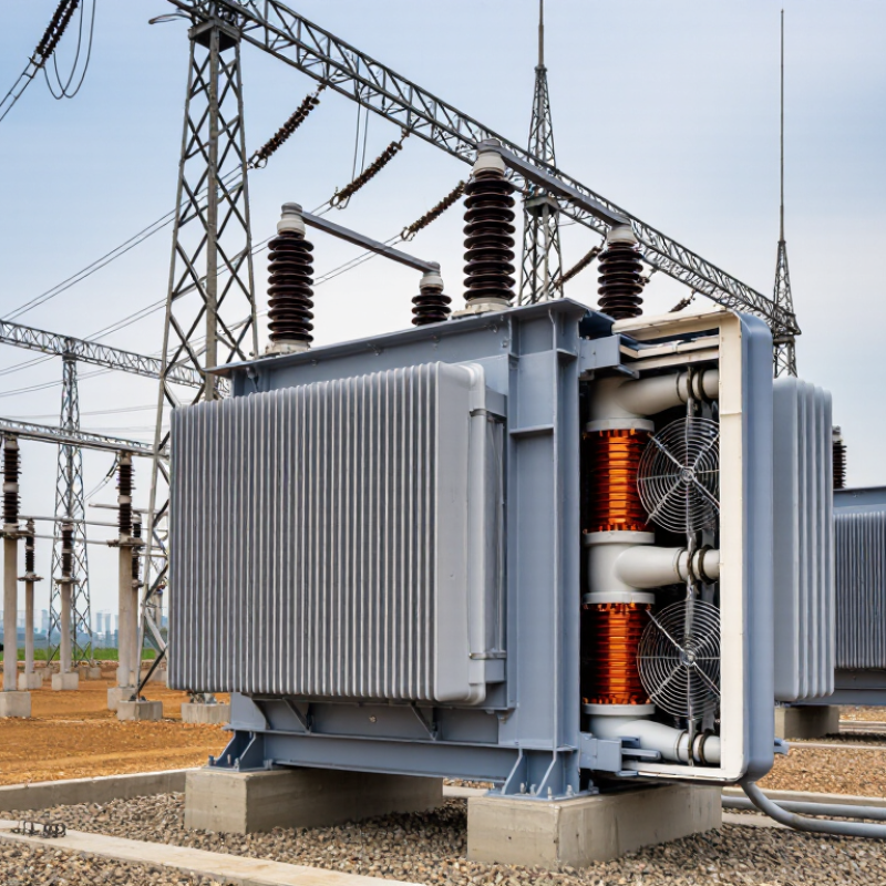
China Top Power Transformer Power Loss Reduction Methods?

China’s Transformer Loss Baseline: 98%–99.5% Efficiency and Core Losses

China Top Power Transformer Power Loss Reduction Methods?

China’s transformer efficiency commonly ranges from 98% to 99.5%, depending on capacity, voltage level, loading, and design quality. This range is a practical baseline, not a guarantee. A small distribution transformer may show higher percentage losses under light demand. Large units often perform better near their rated load.

Core loss continues while the transformer remains energized. It comes from hysteresis and eddy currents in the magnetic steel. Designers reduce it with high-grade grain-oriented steel, thinner laminations, accurate step-lap joints, and controlled flux density. Better core clamping also limits vibration and unwanted heating. In factory inspections, no-load loss testing can reveal assembly problems that drawings will not show.

Load loss changes with current and winding resistance. Larger conductors, shorter current paths, improved joints, and stronger cooling can reduce this loss. Regular voltage checks matter too. Excessive voltage can raise core losses quickly. Digital monitoring helps compare temperature, load, and power factor over time. Still, field data is often incomplete. A clean test report may not represent years of dust, harmonics, or uneven loading. Engineers should measure actual operating conditions before selecting a replacement or redesigning a transformer. Small errors in assumed load profiles can weaken an otherwise efficient project.

Step 1: Cut No-Load Losses with Grain-Oriented Steel Below 0.2 W/kg

China Top Power Transformer Power Loss Reduction Methods?

Step 1: Cut No-Load Losses with Grain-Oriented Steel Below 0.2 W/kg

No-load loss continues while a transformer is energized, even without a connected load. Core steel therefore deserves early attention. The European Commission’s transformer ecodesign studies estimate that transformer losses consume roughly 2% to 3% of electricity use across the European Union. That makes small, permanent savings meaningful.

Grain-oriented electrical steel reduces hysteresis and eddy-current losses through controlled crystal orientation. However, “below 0.2 W/kg” is not a universal operating value. It depends on grade, thickness, flux density, frequency, joint design, and test method. IEC 60404-8-7 and IEC 60076-1 require defined measurement conditions. A specification without test conditions can mislead procurement teams. Engineers should request loss curves at the intended 50 or 60 Hz flux density, not only a single catalogue figure. Core joints also matter. Poor step-lap assembly can quietly erase material gains.

Tips: Compare guaranteed P0 values, test conditions, and tolerances. Inspect burrs, clamping pressure, and corner alignment during production. Field measurements may reveal surprises. That is worth checking. A practical design review should also question whether a thinner steel grade justifies its higher cost and handling sensitivity. DOE transformer efficiency analyses show that reducing no-load losses can deliver benefits over many operating hours, especially in lightly loaded distribution networks.

Step 2: Reduce Load Losses Through Copper Design and Current Density Control

Reducing transformer load loss starts with the copper path. Load loss mainly follows the I²R relationship, so conductor resistance must remain low under operating temperature. A larger copper cross-section lowers current density and reduces heating. However, oversized conductors increase winding dimensions, material use, and manufacturing difficulty.

Practical design begins with measured load profiles, not only rated current. Engineers select a current density suitable for voltage class, cooling conditions, and duty cycle. Lower density often improves efficiency, but it can create longer winding paths. That extra length may offset part of the expected gain. Careful winding geometry matters.

Keep the current path short.

Copper strips or wires should be arranged evenly, with secure joints and consistent pressure. Poor connections create local hot spots and add avoidable resistance. Transposition can limit circulating currents in parallel conductors, especially in larger windings. Insulation thickness also deserves attention. Excessive insulation reduces available copper space, while insufficient clearance threatens thermal and electrical reliability.

Resistance should be checked at controlled temperatures, then corrected to actual operating conditions. Load-loss testing can reveal gaps between calculations and production results. A transformer may pass a design estimate yet perform poorly because of joint resistance, uneven conductor placement, or unexpected stray losses. Field experience shows that small assembly details often decide the final result. Some designs still need revision after testing. That is not failure; it is evidence.

Step 3: Improve Cooling to Keep Winding Hot-Spot Rise Below 65 K

Improving cooling is a practical way to reduce transformer power losses and protect winding insulation. The design target should keep the winding hot-spot rise below 65 K under rated load. This limit requires more than a larger radiator. Engineers must examine oil circulation, air movement, winding geometry, and local heat concentration.

In field inspections, blocked radiator fins often raise oil temperature faster than expected. Dust, paint damage, and poor ventilation can restrict heat transfer. Clean radiator surfaces regularly, and keep clear air paths around the transformer. Forced-air fans may improve cooling, but their control settings must match load conditions. Excessive airflow wastes auxiliary power and may create uneven temperature distribution.

Measure temperatures at several operating points, including peak seasonal load. Fiber-optic sensors or calibrated thermal models can identify dangerous hot spots inside windings. Our first airflow estimate was once too optimistic. A later temperature test revealed a warmer upper winding section. The cooling layout needed adjustment. This is a useful reminder: calculated performance should be checked against real measurements. Maintain proper oil levels, inspect pumps for vibration, and verify fan operation before high-load periods. Small maintenance failures can erase carefully planned loss reductions.

China Top Power Transformer Power Loss Reduction Methods — Step 3: Improve Cooling to Keep Winding Hot-Spot Rise Below 65 K

Calculated engineering reference values showing how improved oil circulation and cooling capacity can reduce winding hot-spot temperature rise at different load factors. The 65 K line represents the design control target used in this comparison.

Lower hot-spot rise reduces thermal aging stress. Increasing radiator capacity, improving oil flow distribution, and maintaining fans or pumps can help keep the winding hot spot below the 65 K target during high-load operation.

Step 4: Apply Energy Standards Targeting 10%–20% Transformer Loss Reduction

Energy standards can turn transformer loss reduction from a vague goal into a measurable procurement requirement. A practical target is 10%–20% lower total losses, but the percentage must reflect the transformer’s real duty cycle. Engineers should separate no-load losses from load losses, then compare both with the applicable national or international efficiency requirements.

During a site audit, record the transformer rating, daily load curve, ambient temperature, and operating hours. A 1,000 kVA unit running lightly all night may waste more energy through core losses than expected.

Specify guaranteed loss values, test methods, temperature corrections, and allowable tolerances in the tender documents. Require independent verification from an accredited laboratory when project risk is high. Small wording details matter.

Do not accept a catalogue efficiency figure alone. Field measurements often reveal different loading patterns. A monitoring period of several weeks can expose weekend demand, seasonal peaks, or poor power quality. Harmonic currents may increase winding losses and heating.

Standards help control design quality, yet they cannot replace operating data. The 10%–20% target is achievable in many upgrades, but it is not automatic. Some early estimates will be wrong. Review them against measured results and revise the specification before the next purchase.

FAQS

Why should transformer core losses be reduced early?

No-load loss continues while the transformer remains energized. Small savings accumulate over many lightly loaded hours. Core steel matters.

Does grain-oriented electrical steel always achieve losses below 0.2 W/kg?

No. The result depends on grade, thickness, flux density, frequency, joints, and testing conditions. A catalogue number alone can mislead.

What should engineers check when selecting core steel?

Compare guaranteed no-load losses, test conditions, and tolerances. Inspect burrs, clamping pressure, and corner alignment. Poor joints waste benefits.

How can copper design reduce load losses?

Load loss follows the I²R relationship. A larger copper area lowers resistance and heating. However, oversized conductors increase cost and winding size.

Why does current density require careful control?

Lower current density usually improves efficiency. Yet longer conductor paths may offset part of the gain. Use measured load profiles, not rated current alone.

What winding details can create unexpected losses?

Uneven conductors, weak joints, and parallel-current circulation can create hot spots. Short current paths help. Transposition may reduce circulating currents.

How can cooling keep winding hot-spot rise below 65 K?

Review oil circulation, airflow, winding geometry, and local heat concentration. Clean radiator fins and maintain clear air paths. A larger radiator is not enough.

What maintenance checks protect cooling performance?

Check oil levels, fan operation, pump vibration, and radiator cleanliness. Measure temperatures during seasonal peak loads. Our airflow estimate may be too optimistic.

Why should calculated transformer performance be tested?

Production details can differ from design assumptions. Temperature testing may reveal a warmer upper winding section. Revision is evidence, not defeat.

Conclusion

Power Transformer Power Loss Reduction Methods focus on improving efficiency from the design stage through operation. A modern transformer can achieve approximately 98%–99.5% efficiency, but reducing both no-load and load losses is essential for long-term energy savings. No-load losses can be lowered by using high-quality grain-oriented electrical steel with core losses below 0.2 W/kg, optimizing the magnetic circuit, and reducing unnecessary flux density.

Load losses can be controlled through efficient copper winding designs, appropriate conductor sizing, and careful current-density management. In addition, an effective cooling system helps maintain the winding hot-spot temperature rise below 65 K, improving reliability and reducing resistance-related losses. Finally, applying energy-efficiency standards and performance targets can support an overall transformer loss reduction of about 10%–20%. Together, these measures create a balanced approach that enhances operating efficiency, limits heat generation, extends service life, and lowers the total energy cost of transformer operation.

Sophia

Sophia

Sophia is a dedicated marketing professional with an exceptional depth of knowledge about her company's products and services. With a keen understanding of market trends and customer needs, she crafts insightful blog posts that not only inform but also engage readers, enriching the company’s online......